Tailwheel Construction


Tailwheel assemblies are probably the most neglected part of a model, especially scale models. Many hours go into construction of a model then a plastic tail wheel bracket is used to mount the tailwheel. Often, the attachment method results in loads being placed on the rudder during landing. This can result in damage to the rudder. A scale-like leaf spring tailwheel assembly can be constructed out of readily available materials in a very short time.

The materials and construction shown here are for a .40 size model but can easily be adapted to any size model. The larger the model is, the more important the tailwheel assembly becomes. A little ingenuity goes a long way in adapting this design. The skills required to construct this tailwheel are well within the realm of the average modeler.

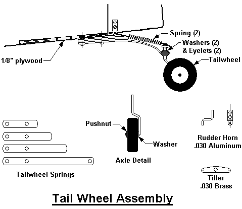
Construction begins with selecting materials that suit the size of the model. In the case of the tailwheel for a .40 size model, all the materials can be found in most shops. The leaf springs are made from a tang of a leaf rake. This material is stiff enough to make a good spring yet soft enough to be drilled. The eyelets and washers came from excess servo parts. The aluminum, brass, and wire are materials left over from other projects. The tiller springs are from old ball point pens. Refer to the drawing below as the construction is described.

TailWheel


The tailwheel caster assembly is bent to shape according to the drawing based on the size of the tailweel being used. In this case, 3/32" (2.4 mm) music wire is used with a 1" (2.5 cm) tailwheel. The wire is bent to clear the tailwheel with a minimum of clearance. The upper stem of the caster is left long and cut off after final soldering. Acid core solder is used for all assembly. A washer is soldered to the axle. An eyelet is placed over the stem and soldered then a washer is soldered to the flange of the eyelet.

The length of the main (longest) leaf spring must be determined first. A cardboard template can be cut 1/4" x 6" (6 mm x 15 cm) and held in place to determine the location of the tailwheel. The main spring is cut with about 1/2" (13 mm) extra which will be removed after final adjustments are made. The curve can be bent into the main spring with the end bent so that it is approximately parallel with the ground when installed. The other springs are cut progressively shorter. The lengths are not critical.

After all of the springs are bent to mating contours, they are clamped together and two (2) 1/16" (1.5 mm) pilot holes are drilled for mounting holes. The springs can be separated and each hole drilled out with a 3/32" (2.4 mm) drill. The holes should be slightly larger than the screws that are to be used for mounting. A 3/32" hole (2.4 mm) hole is drilled in the main spring for the caster assembly.

The tiller is made of .030" (.8 mm) brass so that it can be soldered to the tailwheel caster. The rudder horns are made of .030" (.8 mm) aluminum. The shape and size of the tiller and rudder horns are dependent on the model. The tiller is cut to shape and 1/16" (1.4 mm) holes are drilled in the ends and a 3/32" (2.4 mm) hole is drilled in the center. The rudder horns are bent to shape and a 1/16" (1.4 mm) hole is drilled in the outer leg and two (2) 3/32" (2.4 mm) holes are drilled in the inner leg.

The tailwheel should be assembled to the model and test fitted before the final assembly. The caster assembly is placed through the hole in the main spring. A washer is placed on the stem of the caster onto the top of the main spring, then an eyelet then the tiller. The caster can be turned upside down with the stem in a vise and the tiller on the top of the vise. There should be no slack in the components at this point. Finally, the tiller, the eyelet, and the washer are soldered by allowing the solder to wick between the parts. When this is complete, the assembly should be painted to match the model.

Now the components can be assembled to the model as shown in the diagram. The tiller springs can be stretched to achieve the right amount of tension. The tailwheel is installed on the caster and a pushnut is pressed on. The excess length of the axle and the stem can be trimmed off. The flat of the main spring should be bent so that it is parallel with the ground and the excess trimmed off.

This tailwheel assemby looks good and it is functional. The weight that is added by this type of tailwheel is surprisingly low. The assembly is functionally far superior to plastic tail wheel assemblies and will outlast almost anything that is commercially available.


Return to Construction Guides